To meet the challenge of designing complete power systems, many robotics and embedded teams are starting to look for an integrated alternative to chip-level power design. The motivation is the same one that moved designers from custom processor boards to compute SOMs: time to market, reliability, and the simple fact that power is rarely the product they're building.
This article introduces the concept of a PSOM (Power System On Module) and compares building a power system from chips against integrating one as a module.
You already know this pattern from compute
If you've built anything with serious compute in the last decade, you've used a SOM (System On Module): a complete computing system on a single board, with the processor, RAM, storage, and power sequencing already done, dropped onto your carrier PCB. Nobody designing a robot or an embedded product today lays out DDR memory routing for their main processor. They buy a Jetson, a Raspberry Pi Compute Module, or an i.MX SOM, and they spend their engineering time on whatever actually differentiates their product.
The SOM won because it moved the abstraction boundary. Instead of designing at the chip level, you integrate at the system level: a proven, tested subsystem with a documented interface.
Chip vendors did something similar inside power conversion itself. A modern DC/DC power module puts the controller, MOSFETs, and inductor in one package, so instead of calculating inductor saturation currents and compensation networks for every rail, you place one part and pick capacitors. The IC used on our NanoBuck is an example of this. But a power module is still a component, a single conversion stage. A real product's power system is many of those stages plus protection, sequencing, monitoring, and control, and that system-level integration has stayed a chip-level design exercise.
What is a PSOM?
A PSOM applies the SOM idea to the power system. It puts a complete power system on one module rather than a single conversion stage, and it usually adds a communication interface so your software can configure it and read what it's doing. That describes a family of modules rather than one specific board, and there are two main types today.
A battery PSOM handles everything between the battery cells and your loads:
- Battery management: cell monitoring, balancing, and protection
- Charging: a complete charger with a real input stage, such as USB-C PD
- Fuel gauging: accurate state of charge and state of health
- Regulated output rails: the voltages your system actually runs on
- Safety systems: pre-charge, reverse-polarity protection, and fault handling
- Communication interface: configure the system, control it, and monitor telemetry from your software
A power distribution PSOM is a complete power tree on a module. One input voltage in, multiple managed rails out:
- Multi-rail regulation: for example 12V, 5V, and 3.3V from a single bus, like our Power Pal
- Per-rail supervision: current monitoring, programmable limits, and power-good status
- Sequencing and control: enable and disable rails in software, with a defined startup order
- Protection and fault reporting: overcurrent, overtemperature, and a record of what tripped
- Communication interface: configure rails, control them, and monitor telemetry from your software
These aren't the only possible types. Any complete power function can live on a module this way, but battery and distribution are where the pattern delivers the most value right now.
What every PSOM shares, and what separates it from a stack of power boards, is the interface. Like a compute SOM, a PSOM is programmable infrastructure. You set limits, read telemetry, and wire fault handling into your application software instead of redesigning hardware.
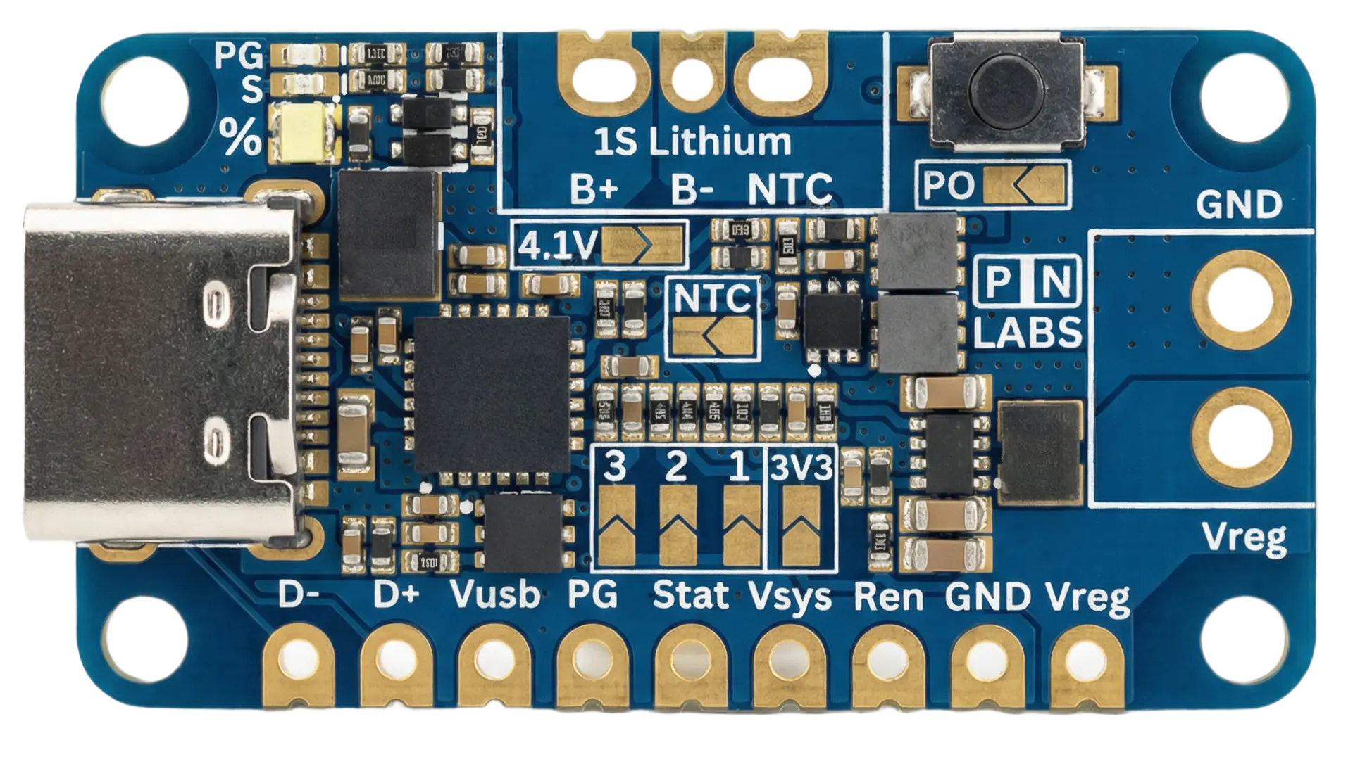
Battery Pal, an example of a PSOM for embedded systems. USB-C PD charging, dedicated cell protection, temperature-managed charge control, fuel gauging, and a regulated buck-boost output on one board: everything between the battery and the load is handled.
What it takes to build this from chips
To see what a PSOM replaces, look at what a production-grade battery power system requires when you start from IC datasheets. The battery case is the most demanding one, but distribution follows the same pattern with fewer chapters.
Battery management. Select a battery monitor and protector IC for your cell count and chemistry, configure the protection thresholds, and design the FET stage for your discharge current with Kelvin-routed current sensing and careful thermistor placement. Get any of this wrong and the failure mode isn't a bug. It's a damaged pack, or a fire.
Charging. Pick a topology that matches your input source and pack voltage. If the input can be above or below the pack voltage, that means buck-boost, one of the harder power designs to stabilize. USB-C Power Delivery adds another controller and another compliance checklist on top.
Fuel gauging. A voltage reading is not a state of charge, especially with flat-curve chemistries like LiFePO4. Real gauging means a dedicated gauge IC and weeks of characterizing your specific cells.
Regulation. Your system runs on 12V, 5V, and 3.3V, not "battery voltage," and each rail is its own converter design. Repeat per rail.
Safety and sequencing. Pre-charge so inrush doesn't weld contacts or brown you out, reverse-polarity protection, and defined behavior for every fault.
Firmware and telemetry. If you want to know remaining runtime, pack health, or why the system shut down, or to adjust output voltages and current limits at runtime, you're now writing embedded firmware: an MCU, a CAN or serial stack, and the host-side integration to match.
Then layout, EMI, thermal validation, and testing. High-current paths next to precision measurement, switching converters next to analog front ends, all sharing one board. Every revision restarts the validation clock.
Each block is individually a solved problem, and the solutions live in application notes and reference designs. Integrating them is different. That's a multi-month project demanding power electronics, battery, firmware, and layout expertise at the same time, and it has to be repeated from scratch for every product. It's the power-system equivalent of designing your own compute board. Possible, and occasionally necessary, but almost never the best use of your team.
The same system with a PSOM
With a PSOM, that entire walkthrough becomes an integration task:
- Connect your battery pack to the module.
- Wire your loads to the regulated rails.
- Configure limits, chemistry, and behavior over the communication interface.
- Subscribe to telemetry like state of charge, current, temperatures, and faults in your application software.
The engineering problems don't disappear. They're solved once, by a team that does nothing else, and validated across every unit shipped. Your battery gets protection thresholds set by battery engineers. Your charger topology is already stable. Your fault behavior is documented and tested. And because the interface is software, the power system evolves with your product: new limits, new charge profiles, and new fault handling without a board spin.
A one-rail, fixed-function device may not justify a PSOM. But the moment your product has a battery, multiple rails, charging, and any need for the system to communicate about its own power, the cost of ownership of a chip-level design overwhelms the module's price. You're paying the BOM plus months of specialist engineering time plus revalidation on every revision. Mobile robots are the clearest example, and the same math applies to industrial automation, remote monitoring stations, field equipment, and connected embedded devices.
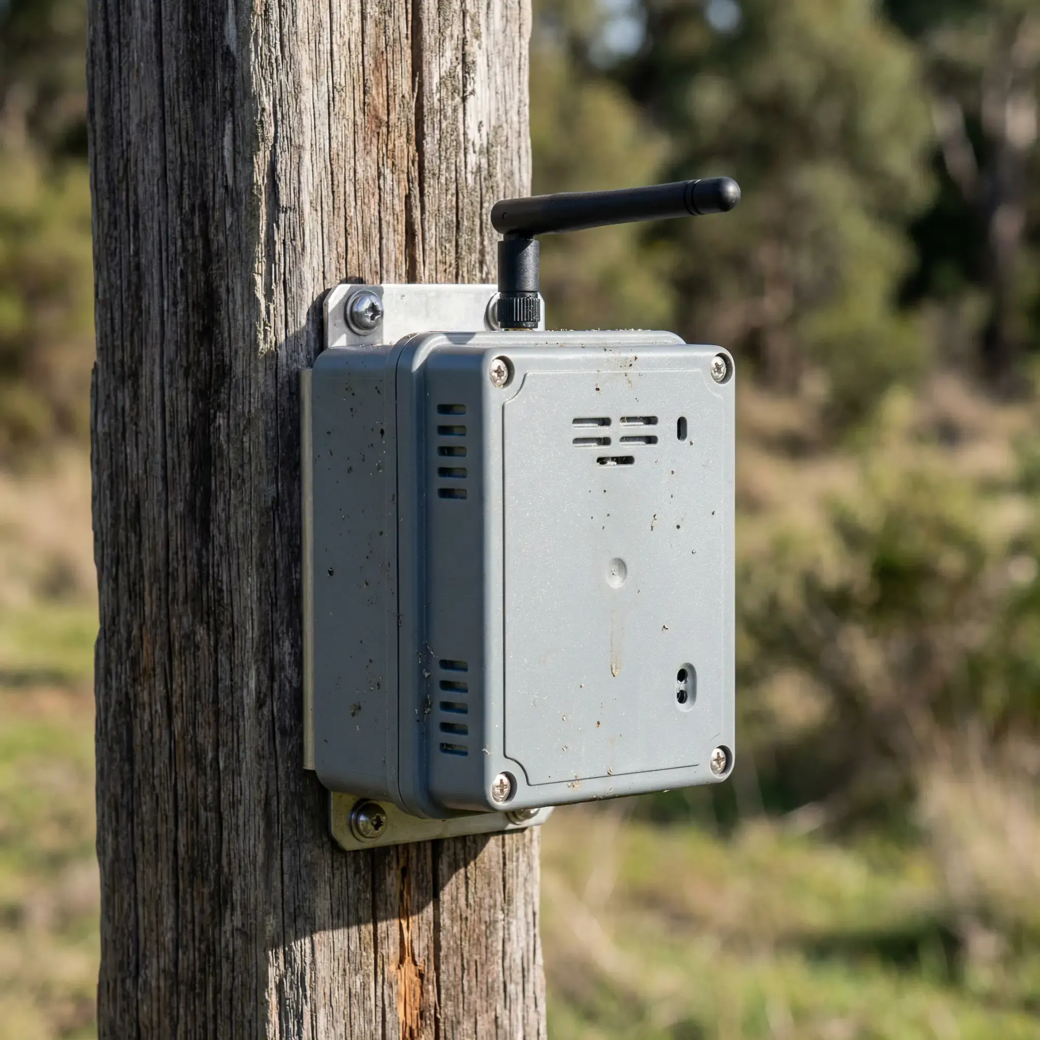
Battery-powered systems whose builders differentiate on software and function, not on power design. This is where the PSOM case is strongest.
Why give it a name?
Because the mental model already exists. Nobody designs their own flight controller anymore, and nobody routes their own DDR4 RAM. Compute became a SOM. Motor control became a module you configure; ask anyone who's used a VESC or an ODrive. Power, the subsystem every one of those depends on, is the layer still being redesigned from application notes, product after product.
A PSOM is the missing piece of that pattern: the power system as a component. Buy it, mount it, and program it, then spend your engineering on your product.
Where PN Labs fits
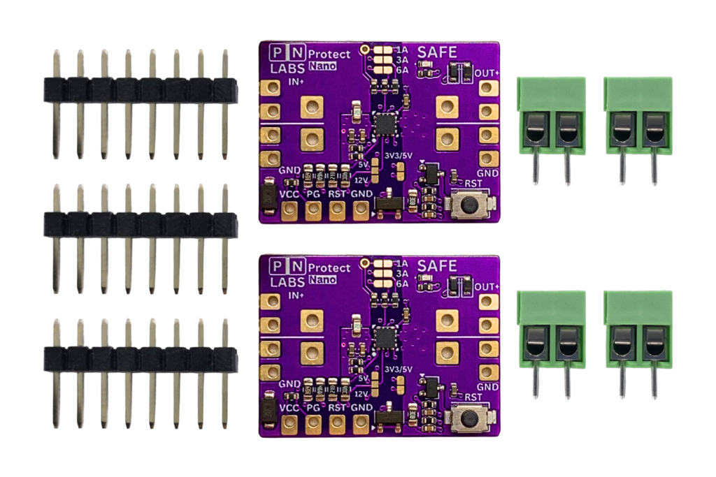
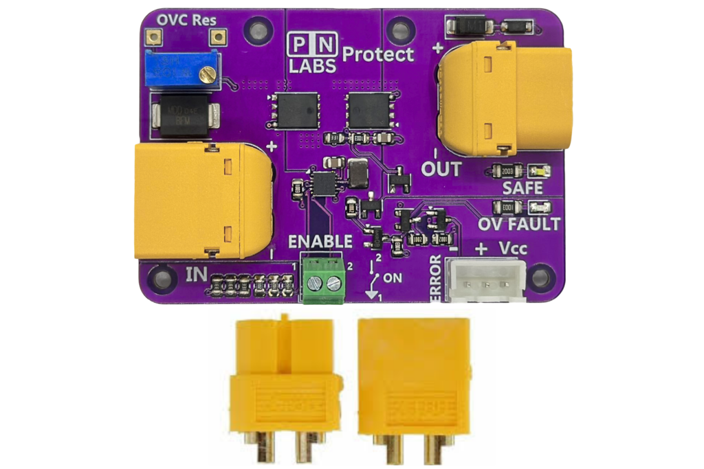
This is the thesis PN Labs is built on. Our modules (Battery Pal, Power Pal, Protect, NanoBuck, Protect Nano) each solve one block of the power system as a tested, documented module with no corners cut. Most of them are not a full PSOM. Those are coming, in both simple and more advanced forms. And because a power system is a long-term commitment, we can guarantee long-term production availability on request, so the module you build your product around today is still there for tomorrow's production run.
Battery Pal is the embedded-scale expression of the battery PSOM idea: USB-C PD charging, dedicated cell protection, fuel gauging, and a regulated 3.3V or 5V output for single-cell lithium designs, all on one board that works the moment you apply power and solders onto your PCB as a component. If you're building a wireless sensor node, a handheld instrument, or a small robot controller, it replaces the entire chip-level walkthrough above at the single-cell scale. Power Pal covers the distribution side, with one wide-range input and three simultaneous rails with protection and power-good monitoring. A complete power tree on a module.
The full software-connected PSOM is where this line of thinking leads: a complete battery power system for multi-cell products, with battery management, charging, regulated rails, safety systems, and CAN telemetry and configuration on one module. That's what we're building next.
Battery Pal is where this starts, and it's only the beginning.
Join the Battery Pal WaitlistAnd if you're building a battery-powered robot or embedded product and you're tired of redesigning power, we'd genuinely like to hear what your power system looks like today.