The Active Power Protection Module (APPM) is an adjustable analog power protection module. It is designed for overvoltage, undervoltage, reverse polarity, and short circuit protection. No black box ASICs. Just comparators, FETs, fuses and voltage references.
The module is a culmination of nearly a year as an electronics student, working in my free time. This design was born after destroying a smart servo motor, by applying too high of a voltage.
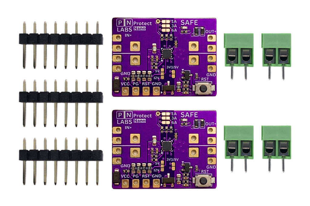
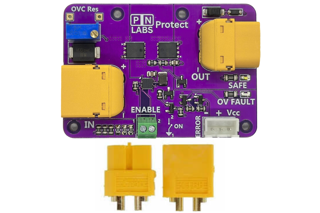
For those who are looking for the finished product that is now sold by PN Labs, check out the Protect and Protect Nano.


📝 Overview
The APPM is an electronic protection module featuring back to back P and N channel MOSFETs to safeguard DC-powered electronics from overvoltage, reverse polarity, and overcurrent conditions.
It sits between your power source and load, continuously monitoring input conditions and disconnecting the load if unsafe voltage levels are detected. It also features a spot for a 6.35 x 35 mm cartridge fuse up to 15 A.
The APPM is yours to download, build upon, and learn from, as it is perfect for 5–24 V systems and operates with good efficiency. PN Labs also have a limited number of already prepared modules available for purchase, if you want one already assembled.
✅ Key Features
- Adjustable Over and Under voltage Protection (5–24 V):
Set your cutoff thresholds by turning the onboard potentiometers while measure the voltage references using the equation. When input voltage falls outside the allowable range, the APPM comparator automatically shuts off the blocking transistor and auto-recovers when conditions normalize. - Reverse Polarity Protection:
Uses an automotive-grade P-channel MOSFET for efficient reverse polarity protection. - Optional Fuse:
Remove the SMD jumper and attach a 6.35 x 32 mm cartridge fuse to the onboard holder. The holder is rated up to 15 A. - Error-Signal:
Low impedance error signal that detects over/under voltage conditions with user-configurable voltage levels of 1.8, 3.3 and 5 V. You can source about 15 mA through this pin. - Quad Status LEDs:
- SAFE = Power is safely flowing
OV FAULT = The input voltage is above the allowable threshold. Adjust the OV potentiometer or lower the input voltage.
UV FAULT = The input voltage falls below the allowable threshold. Adjust the UV potentiometer or raise the input voltage.
- POLARITY FAULT = The input is connected with the wrong polarity.
⚙️ Adjusting the Voltage Limit
The APPM allows users to precisely set the over and under voltage cutoff thresholds by adjusting the onboard potentiometers, which adjusts the reference voltages.
💡 Cutoff Equations
To set the cutoffs, start by calculating the needed OV reference voltage using the equation below. It is important that you do this before setting the UV reference since it is divided by the OV reference voltage.
Calculate the desired cutoff voltage using the following formula:
OV Voltage Limit = 3.14* VREF+
VREF+ is measured from its pad with respect to ground.
UV Voltage Limit = 2.7*VREF-
VREF- is measured from its pad with respect to ground.
The voltage between the test points can be measured with a multimeter, while adjusting the potentiometers with a screwdriver. This provides fine-tuned control over the protection threshold.
Important: Always adjust the OV limit first since the UV limit is derived from further dividing down the OV reference voltage (VREF+).
🚨 Over and Under voltage Protection Behavior
When the input voltage falls outside of the configured OVC limit:
The APPM disables the output, turning the SAFE LED off.
The OV or UV Fault LED turns on
The ERROR signal pin goes high to the user selected voltage, if one of the jumpers is soldered.
The module will automatically re-enable the output once the input voltage falls back into the allowable range.
⚡ Reverse Polarity Protection Behaviour
If the module is subject to reverse polarity on the input, the POLARITY FAULT light will turn on and the P channel MOSFET will be turned off, blocking power from flowing back to the load.
🟢Normal Operation
When operating within safe voltage limits:
The Safe LED is illuminated
The ERROR signal is held low.
📐 Product Specifications
Operating Voltage: 5 – 24 V DC, blocking voltages up to 30 V.
Maximum Continuous Power: 445 W
Maximum Continuous Current: 18.5 A @ 25 °C ambient. 15 A if using the fuse holder.
See thermal image and data below for performance at 18.5 A.
⚠️ Thermal Warning: Ensure the board temperature does not exceed 110 °C under any condition.
Thermal Testing (5V 18.5A @ 25C Ambient - Least Efficient)


The board has overall dimensions of 50 x 65 mm. Four M2 mounting holes are included.
The active power protection module is a simple, yet effective protection device. It uses back-to-back P and N channel MOSFETs and digital logic to provide a remarkably efficient power path with user-oriented status indicators.
A P-channel MOSFET was chosen to provide reverse polarity protection with higher efficiency than a Schottky diode. An N-channel MOSFET was chosen for its lower drain-source resistance when fully saturated due to the higher electron mobility of n type silicon, and a corresponding gate driver was chosen to allow the gate voltage to be boosted higher than the source.
An LM324 quad op amp was chosen as the main IC because it can be configured to work as a dual comparator up to 30 V and also provides a low-impedance digital error signal capable of driving a few mA to light LEDs and the like.
A 33 V bi-directional TVS diode was used to clamp voltage transients applied to the input of the board. You could probably get away with just using one just fine.
Logic level MOSFETs are used appropriately to turn on or off LEDs based on power input conditions. See the schematic to understand more about how they work.
A flyback diode was placed in case of inductive loads being present, and a reverse biased Zener diode was also added in series with that to raise the flyback voltage and thus increase the rate at which the flyback energy is dissipated during turnoff.
Everything else on the board are just passives which support the work of the already mentioned devices.