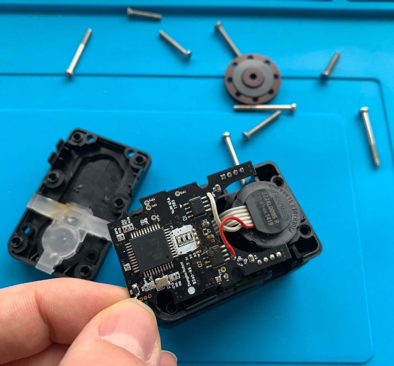
Why are things done this way? It costs less than 40 cents and takes minimal space to add a simple part from Texas Instruments that would solve this problem. There are some minor technical complications (thermal management) from adding it, but nothing that can’t be overcome. Instead, the designers chose to leave out these features because when an incorrect voltage is applied, the blame falls on the user – and that means more servo sales. These are predatory design tactics that exploit the lack of technical knowledge and best practices by new users, discouraging people who are just starting out in electronics.
It was my mistake. I was the one who didn’t check before connecting it. However, that doesn’t mean this is how things have to be.
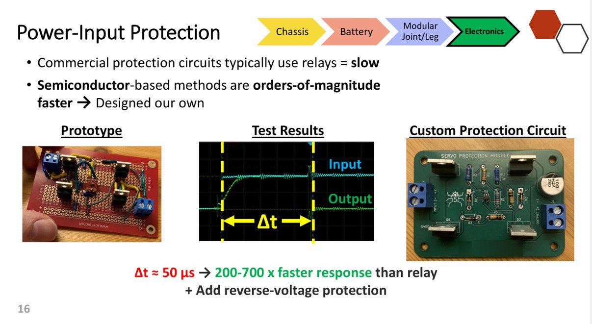
After searching for overvoltage protection modules online, I was frustrated to find that all available options were either using under-performing parts, rated for low voltages, or using relay-based switching. To begin, these modules are slow to act, inefficient, and outdated. Given that our project cost about $6000 CAD to build (the majority of which was electronics), I was not going to let its success or failure hinge upon the performance of an $8 relay module from Amazon. As a result, I hacked together a primitive MOS transistor-based prototype on a breadboard. Although it was inefficient and scrappy, it nonetheless proved fast and accurate – and I ended up making it on a PCB before being integrated on the final robot. Shown below is a slide from our final presentation showing the initial prototype and final result:
Realizing that this new device had potential to protect people’s electronics and was filling a niche not covered by existing products, I set out to improve on my first prototype and see if it could have any commercial value.
It wasn’t easy. Many people were skeptical that it was even possible to build a small business around circuit protection/power management.
“Isn’t that one of the most basic things electrical engineering students learn on day one?” one of my friends asked.
“Let me know when your design sells for 50 cents on Temu,” joked someone else.
But I pushed ahead. After ten months of learning PCB design and refining the overall protection techniques, I finally had a fully analog design with 95% typical efficiency, offering overvoltage, undervoltage, reverse-polarity protection and a fuse for over-current.
Around the same time I was finishing this project, I reconnected with Ethan, an electrical engineer working in the consumer electronics industry. He mentioned that he wanted to start an electronics company. We teamed up, but when I showed him my design, he said it was solid but far too expensive to manufacture and sell sustainably. I had used a P-channel FET that gave good efficiency but accounted for 35% of my entire BOM cost!

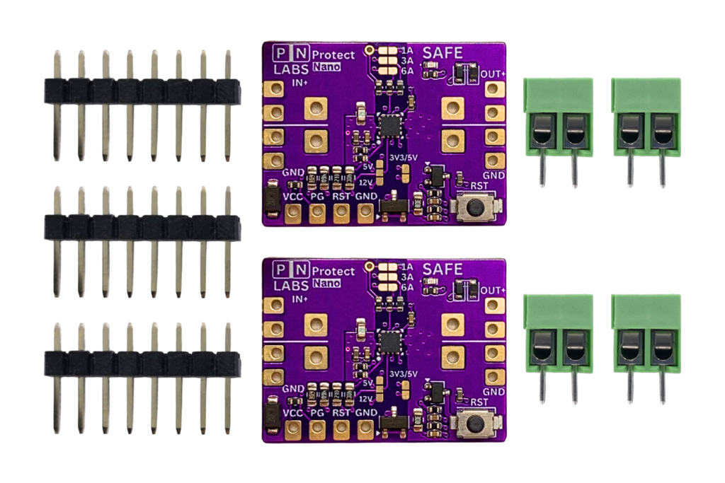
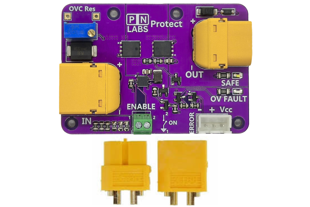
So, I went back to the drawing board and redesigned the entire system around an ASIC that could do everything I needed – cheaply and reliably. After a few iterations, I had the Protect module – something that worked for over-voltage, reverse current and reverse polarity with up to 99% efficiency and a realistic production cost. Ethan, my now co-founder, made a YouTube video demonstrating the module, and it was seen by over 10 000 people.

The response was mixed. Some commenters didn’t understand why a fuse wasn’t enough. One person outright hated it, saying:
“Instead of using common sense, you made some stupid contraption to make yourself less diligent in your work!”
We didn’t care. We knew the value of what we were building — because we’re makers ourselves, and we use our own products in our designs. Our modules don’t just protect against overvoltage; we have made 3 Protect series modules now that also handle reverse current, reverse polarity, and overcurrent protection at a range of power levels. Using them effectively and making sure people know about them comes with some education and proper documentation. So that became our next focus.
Today, our modules have helped customers in multiple countries who work on building custom flight simulators, medical equipment, ocean-exploration technology, and many other projects, even though we’ve only just started.
We strive to fill existing niches with the kind of technology makers deserve, and we believe no one should suffer from outdated practices, bad design habits, or predatory engineering shortcuts – especially when better alternatives exist.
If that sounds like you, you’re one of us.
Here are some ways that you can help support our mission (without spending a dime):
- Follow us on our social media channels (Reddit, YouTube, Instagram, Facebook, TikTok).
- Tell a friend.
- Tell us about a problem you’re facing that you think our products or services might be able to solve. (Please note: we don’t work on anything that normally operates above 60 V DC or 1.8 kW, and all relevant safety regulations still apply.)