How using a TP4056 Battery Charger can Ruin Your Project

TP4056-based modules are the cheapest single-cell lithium battery charger available on the market. Commonly sold in packs of 10 on Amazon, e-Bay, AliExpress and other online retailers, they are a classic buy for most DIY electronics hobbyists when first trying to work with a lithium-battery in their project.

But they’re just that: chargers. In most cases, hobbyists drastically overestimate their utility and then end up in a potentially dangerous situation, and lithium batteries can easily catch fire if abused.

At PN Labs, we have extensive experience working with lithium batteries and care about people using them correctly, so we’ve written this article to discuss how you can use one safely, and where most people get it wrong.

TP4056 Module Breakdown

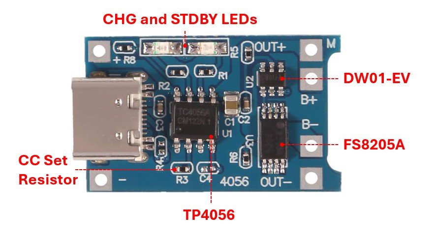
Your standard TP4056 Module looks like this:

What these parts do:

  • TP4056 Charger IC: Implements a CC/CV (constant current / constant voltage) charging profile suited for single lithium-ion cell. During bulk charging, it drives a regulated current set by the programming resistor (labelled R3 above). As the cell voltage approaches 4.2 V, the charger holds the voltage constant until the current decays to 1/10 of the programmed charge current. The IC also includes thermal regulation: automatically lowering the charge current if the die temperature exceeds roughly 120 C to protect itself.
  • DW01-EV Protection IC: drives the MOSFETs and cuts off if the cell is above 4.30 +/- 0.05 V or below 2.4 +/- 0.1 V. It also features overcurrent shutdown by sensing the voltage drop across the MOSFETs with a dedicated pin.
  • FS8205A Dual n-channel MOSFETs: Routed on the PCB in a back-to-back (common-drain) configuration for bidirectional current control.

Overall TP4056 Performance

The TP4056 module can be expected to:

  • Provide a safe CC-CV charge (although without temperature feedback) over USB for a single cell up to 4.2 V when no external load is connected, although often it will be less than 1 A because of thermal constraints.
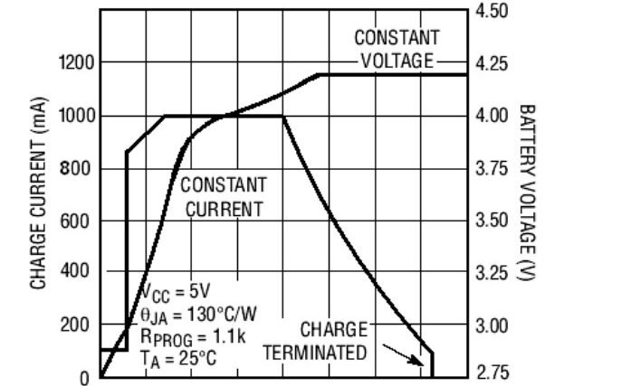
    CC/CV Charging profile of a lithium cell from a TP4056 datasheet
  • Get a little hot due to the linear regulation of the charge current, which is not a problem if it is not touching the battery or anything temperature-sensitive.

Incorrect Uses of the TP4056 Module

 Here are the most common incorrect uses of the TP4056 module that we see online and through people we talk to:

  1. Simultaneous Charge and Use applications. There is no separation between the charge current and the load current on the TP4056 (no power-path management). This means that loads placed on the cell output will confuse the charger, because the termination current on the CV hold step of the charge is never reached. This results in a trickle-charge scenario which greatly reduces battery lifetime.
  2. Relying on the DW01 protection IC as over-discharge protection for your battery. 2.4 V is far too low for protecting lithium cells designed to operate from 3.0-4.2 V. The designers of the IC likely intended it to be used as a last resort, or with cells that have long leads and thus a lot of voltage drop. It could be okay if 2.4 V is briefly reached under high load conditions where the true equilibrium voltage is closer to 3.0 V, but a slow discharge will certainly damage the cell if it was gradually brought to 2.4 V.
  3. Putting the charging board in close proximity to the cell: The heat generated from the linear regulator can start a fire if directly in contact. 


All these problems make you question why even design a board like this in the first place. The TP4056 modules are intended to be used as charging modules, and they do an adequate job at just that.

I actively use them when needing to charge a cell to 4.2 V all the time. The problems appear when people extend the intended use case. The worst part about all this is that battery cells fail slowly, meaning that you can get away with doing things wrong for a while, until the battery fails prematurely or something goes sideways.

As an Alternative:

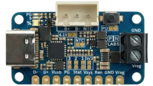
Our Battery Pal module is an all-in-one battery charger, protection board, and voltage regulator for 3.0-4.2 V lithium cells capable of 3.3 or 5 V outputs up to 1.5 A continuous, perfect for embedded applications.

Take a look at our pre-launch page here!

Share the Post:

Other Posts

Blog
Nick

Over-Current Protection Circuits that are Better than Fuses

Passive fuses are commonly implemented in electronic systems to melt during over-current conditions. This prevents excess energy from flowing into the system, however, they are often imprecise and insufficient for protecting real-world systems on their own.  This article explores why fuses are inherently limited, and explains several different circuit topologies that can be built or bought that offer more precise over-current protection. Note: Schematics presented here illustrate fundamental architectures and are not tailored towards any specific application. A technically qualified person should always test the final product to determine suitability for any safety-critical or high-stake applications. Why are fuses

Read More
Blog
Nick

Continuous Over-Voltage Protection Circuits

Continuous over-voltage is a common way circuits get destroyed because fuses and transient over-voltage protection devices like MOVs, TVS diodes and GDTs are not well suited to protect against them. In this article, we will discuss the pros and cons of different circuit topologies that are specifically for continuous over-voltage protection. Voltage Protection Topologies Over-voltage protection circuits can broadly be divided into two categories: transient and continuous. In this article, we will focus on methods for protecting against continuous overvoltage. Different topologies covered: SCR/TRIAC Crowbar Passive and Active Clamping Circuits Switched Disconnect (MOSFET or Relay) Voltage-Triggered Load-Dump Circuits SCR/TRIAC

Read More
Blog
Ethan

Why Overvoltage Protection Is Critical for Your Circuit (and 3 Ways to Add It)

Every electronics engineer eventually learns this lesson the hard way: you plug in power, a faint (or extremely loud) “pop” echoes through the room, and the circuit dies instantly. That’s the story of overvoltage. It is when the voltage applied to your circuit exceeds what your components can safely handle. Whether it’s from a mis-wired power adapter, an inductive kickback, or a power surge from a bench supply, even a momentary spike can destroy sensitive semiconductors. In professional designs, overvoltage protection (OVP) is not optional but a required part of reliability engineering. Adding overvoltage protection to your circuit is

Read More