


Description
📝 Overview
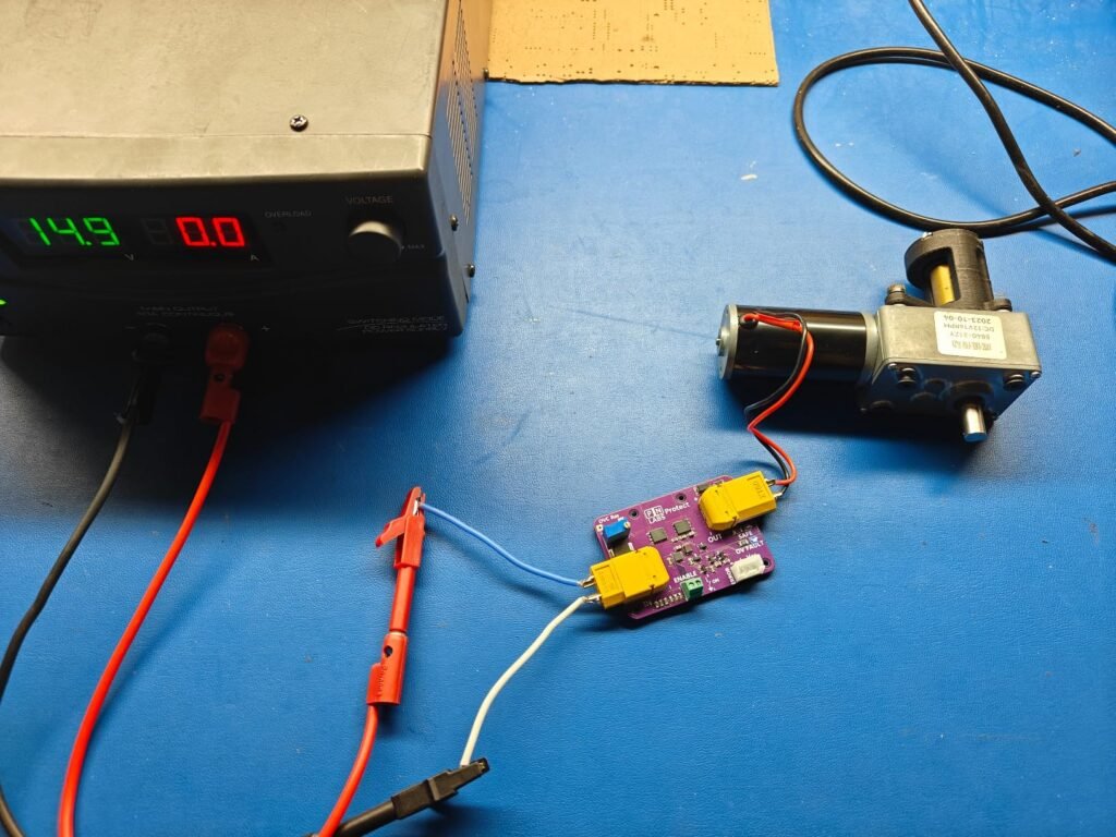
The PN Labs Protect is a compact, high-performance DC power protection module designed to safeguard your electronics from overvoltage, reverse polarity, and power source mishaps.
It works by sitting between your power source and load, continuously monitoring the input voltage against the adjustable reference and disconnecting the output if unsafe voltages are detected, preventing costly damage.
In addition to continuous monitoring, the built-in soft-start feature intentionally adds a time delay during power on, creating a window where the power supply is ramped to its steady state value while being monitored. This means that if the threshold is set correctly, the output will never see the full applied voltage before being switched off.
Perfect for 5–30 V systems, Protect is ideal for robotics, makers, and industrial applications alike.
Featured in:
✅ Key Features
- Adjustable Overvoltage Cutoff (5–30 V):
Set your cutoff threshold by turning the onboard potentiometer. When input voltage exceeds the limit, Protect automatically shuts off the output and auto-recovers when conditions normalize. Typical accuracies of 3% or better are attainable by attaching a high-tolerance fixed resistor and using the given equation. - Reverse Polarity & Reverse Current Protection:
Acts like an ideal diode with only a 13.5 mV typical voltage drop up to 14 A. Prevents damage from incorrect power connections and supports paralleling power supplies for redundancy (ORing). - Solid-State Reliability:
No relays, no clicks. Just dependable, fast-acting MOSFET control. Designed for longevity and high reliability in demanding applications. - Power Switch Capability:
Use a low-current mechanical switch to toggle high-power loads via the Enable terminal block. No bulky high-current switches needed. - Microcontroller Fault Output:
Open-drain fault pin goes LOW during an overvoltage event—ideal for system diagnostics, alerts, or shutdown logic. - Dual Status LEDs:
- SAFE = Power is safely flowing
FAULT = Overvoltage fault detected and output disconnected
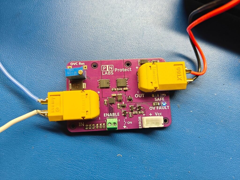
Compact & Mountable:
60 x 42 mm PCB with four M2 mounting holes. XT60 connectors make it easy to install inline with your system or stack multiple modules for power ORing.
⚙️ Adjusting the Overvoltage Cutoff (OVC)
Overvoltage Resistance (OVC Res) Calculator
The Protect module allows users to precisely set the overvoltage cutoff threshold by adjusting the onboard potentiometer, which controls the resistance labeled OVC Res.
💡 Cutoff Equation
To calculate the desired cutoff voltage, use the following formula:
OVC Res = (OVC – 1.95) / 2.89
OVC Res is in kilo-ohms (kΩ)
OVC is your desired overvoltage shutdown voltage in volts (V)
You can measure the resistance between the test points with a multimeter while adjusting the potentiometer with a screwdriver. This provides fine-tuned control over the protection threshold.
Important: Always power off the Protect module before making adjustments to the OVC resistor to ensure current flow through the multimeter doesn’t affect its reading.
🚨 Overvoltage Protection Behavior
When the input voltage exceeds the configured OVC limit:
The Protect module disables the output within microseconds
The OV Fault LED turns on
The FAULT signal pin is pulled low (open-drain to GND)
The module will automatically re-enable the output once the input voltage falls approximately 0.5-1 V below the OVC limit, allowing seamless recovery after transient spikes.
⚡ Paralleling Protection Behavior
⚠️ Why would you need to use a Protect module instead of just directly connecting in Parallel?
When two unequal voltage sources are connected in parallel, the higher voltage side will attempt to charge the lower voltage side to bring them both to the same potential.
This uncontrolled flow of current can damage power supplies that are not designed to handle this, as the internal control loop will now try to compensate for what the other power supply is doing. In the case of a battery, an unregulated and potentially dangerous current spike will flow that may be higher than the maximum charging current of the battery, thereby damaging it by plating lithium and contributing to early failure.
The Protect module has an internal comparator which senses the voltage drop across the first MOSFET and shuts it off within microseconds if there is any reverse current flow detected, thereby saving your power supply.
In order for the power supplies to share the load, we have found that they generally need to be within 0.5 V or less of each other.
To operate the Protect module in Paralleling mode:
Use one Protect module per power source.
Set the OVC (overvoltage cutoff) limit on each module, or disable the limit by turning the OVC resistor to its maximum resistance.
Connect each power source to its own Protect module.
Join the output terminals of all Protect modules together to form the combined output.
(Optional) Add a switch to the Enable terminal on each module to individually turn power sources on or off, as described below.
🟢Normal Operation
When operating within safe voltage limits:
The Safe (green) LED is illuminated
The FAULT signal pin is pulled high to Vcc (via an internal pull-up)
🔌 Optional: High-Power Switch Function
The Protect module can also act as a main power switch for your system. Simply connect a single-pole single-throw (SPST) switch to the Enable terminal block:
Open switch = Module enabled (normal operation)
Closed switch (connect points 1 and 2) = Module enters low-power mode and disables output
This allows you to toggle high-current power delivery using a compact, low-current mechanical or digital switch.


I’ve had issues with other overvoltage protection modules in the past. Many of them claim to handle up to 36V, but the relays are clearly marked with a maximum voltage which is usually 14V or 25V. After only a couple of weeks of use, the other one I tried died. It claimed a max input voltage of 36V but the relay label stated a maximum voltage of 14V DC. I was using 24V.
After trying a couple other modules for my project, I went with this one because is its simpler to set up with the included connectors, keeps its programmable threshold even if you lose power, and uses transistors instead of relays which are faster and more reliable.
It works well and the potentiometer is easy to adjust to get the desired voltage cut-off. I intend to use it for overvoltage protection on a switching power supply which I use as a desktop power supply for 12V applications. The external “ENABLE” at the terminal block will be useful to connect a power switch.
I experimented with the device at various voltage ranges to provide protection when powering microcontrollers and a motor. The switch from green to blue light is a nice visual indicator to know that the voltage cut-off range is exceeded and something needs to be modified or checked.
I wish the import duties were more prominent up front on shipments to the USA. The postage of $15 fits the normal these days but the tariff and paperwork fees add another $40. That makes my $23 board cost me $78. Nice product but too expensive to acquire.
Hello Bruce,
We apologize for the confusion surrounding the shipping process for your order. Your purchase was placed just before we completed a major update to our shipping system. The new system makes it much clearer when tariffs apply for shipments entering the United States and includes tools to calculate and collect those fees upfront, helping customers avoid the high brokerage charges often added by couriers such as UPS.
To take responsibility and make this right, we have issued a full refund for your order, which should offset the unexpected UPS fees that were not disclosed at the time of purchase.
P.S. We are actively working to secure a U.S. based logistics partner so customers in the United States can avoid high shipping costs, import fees, and tariffs.
– Nick