Over-Current Protection Circuits that are Better than Fuses
Passive fuses are commonly implemented in electronic systems to melt during over-current conditions. This prevents excess energy from flowing into the system, however, they are often imprecise and insufficient for protecting real-world systems on their own.
This article explores why fuses are inherently limited, and explains several different circuit topologies that can be built or bought that offer more precise over-current protection.
Note: Schematics presented here illustrate fundamental architectures and are not tailored towards any specific application. A technically qualified person should always test the final product to determine suitability for any safety-critical or high-stake applications.
Why are fuses often inadequate?
In order to effectively protect your circuit, you need to distinguish whether the problem is excess voltage or excess current.
Many modern electronics are built with discrete MOSFETs or use integrated CMOS architectures. As a result, their delicate gate-oxide structures can easily break under excess voltage far faster than any current-limiting device could respond. In that case, you can read our article about continuous over-voltage protection circuits.
Fuses are pieces of resistive material that are sized to melt open above a certain operating current, and below their maximum rated voltage. They do nothing to limit the voltage applied to a circuit. They also require a minimum time where the current is exceeded before the fuse can interrupt (this is referred to as the I2t rating). Shown below is a typical time to trip curve for a general purpose fuse:
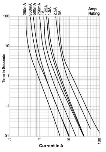
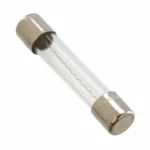
This particular fuse is rated for 3.5 A. At that current, it can take over 4 hours to blow. Even at twice the rated current, it still takes up to 5 seconds, meaning that fuses are not precision devices and only protect against worst case scenarios.
Over-Current Protection Techniques Covered
Over-current protection mechanisms can broadly be divided into 3 categories: sacrificial devices, passive resettable limiters, and active interruption methods. As sacrificial devices all involve fusible elements, this article will only discuss the most commonly used devices from the latter two categories. These devices include:
Passive Resettable Limiters:
- Polymer PTC fuses
- Thermal-Magnetic circuit breakers
Active Interruption Techniques:
- SCR Crowbar
- Solid-State Electronic circuit breakers (e-Fuse / Load Switch)
- Active-current limiters
- Pyro-fuses
Passive Resettable Limiters
Passive resettable limiters interrupt excessive current flow, and restore functionality on their own or with minimal intervention. This makes them common in applications where clearing an overcurrent condition is a routine part of operation that should not result in servicing.
Polymeric Positive Temperature Coefficient (PPTC/PTC) fuses
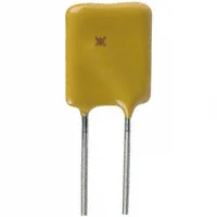
A PPTC fuse is the simplest passive resettable limiting device. It works by adding significant series resistance to the current path as the device heats up. A typical datasheet specifies:
- Hold current: Maximum current that the device will pass without interruption.
- Trip Current: Minimum current that will reliably activate the fuse under some specified test conditions.
- Min, Max and 1Max Trip Resistances: the minimum and maximum device resistance under normal operating conditions, and the max resistance of the device 1 hour after being tripped.
- Rated Voltage: the maximum voltage drop that can be present across the device terminals without a voltage-based failure mode.
- Activation temperature: The temperature at which the fuse must reach to significantly activate.
Pros of PPTC technology:
- Automatically resetting, useful for applications where faults are expected to be temporary, replacement is inconvenient, and a hard-interrupt isn’t strictly necessary. E.g. locked-rotor protection for a DC motor.
- Current-limiting instead of interrupting, which gradually reduces the rate of change of current. This is useful in systems with high inductance (e.g. motors), where fast interrupts from conventional fuses can cause significant voltage spikes along the bus due to inductive kickback.
- Passive and Inexpensive! Implementation is as simple as finding the correct part and dropping it in series with your circuit. Available in a plethora of through-hole or SMD packages for cents.
Cons:
- Leakage current still exists, and is not always safe: E.g. in lithium battery protection having a persistent leakage current can kill the battery by over-discharging the cell through the fault.
- Response time is slow compared to active techniques: Response time is governed by thermals, so lag is inherent. Typical response times specified by manufacturers are in the single to low 10s of seconds.
- Ambient temperature sensitivity: Effective trip current shifts with operating environment. A device rated for 500 mA might trip at 400 mA in a hot enclosure, complicating design considerations.
- Reset time: The device needs to cool to reset.
- Higher series resistance than a regular fuse in normal operating conditions: A typical 5×20 mm cartridge fuse rated for 5 A might have a series resistance of 5-15 milliohms, depending on its intended response time. Comparing that to a typical 5 A PTC fuse, we see that it has 15-34 milliohms of ESR under normal operating conditions.
Thermal-Magnetic Circuit Breakers
Thermal-Magnetic circuit breakers employ no active circuitry and are a marvel of engineering. They combine thermal expansion and magnetic induction mechanisms to sense overcurrent conditions:
- Thermal Element (Bimetallic Strip): A high-expansion metal (Brass or nickel-chrome alloy) bonded with a low expansion metal (commonly Invar) to create a thermal gauge which bends with increasing temperature. When the strip displaces enough due to self-heating, a snap-action mechanism trips the breaker.
- Magnetic Element (Solenoid): A coil that generates a magnetic field proportional to current. During a sudden, severe short circuit, the field becomes strong enough to instantly pull a trip mechanism, responding far faster than the thermal element could.
Together, they protect against both slow overloads and instantaneous faults.
Here is an in-depth teardown and explanation on YouTube, from Controls and Automation!
Pros of Thermal-Magnetic Circuit Breakers:
- Dual-mode protection that features slow over-load protection and fast short-circuit interruption.
- Not dependent on electronics! They are just cleverly engineered pieces of metal and plastic.
- No external power is required.
- There are known trip curves with strong fault interrupt ratings.
Cons:
- Slow for moderate overcurrent. A 150% overload may take seconds to trip.
- Performance fluctuations due to ambient temperature at low overcurrent, as the thermal aspect of the breaker is affected.
- Fixed operating point, not dynamically adjustable.
Active Interruption Techniques
Active interruption circuits are specifically designed to interrupt currents in the fastest time possible. They are used in applications where speed is critical, or the system requires precise, controllable interruption.
SCR-based Crowbar Circuit
Crowbar circuits are a classic overvoltage protection circuit, but they can be tripped based on over-current as well! The schematic below uses a comparator to measure the voltage drop across a sense resistor, and compare it to a calculated reference:
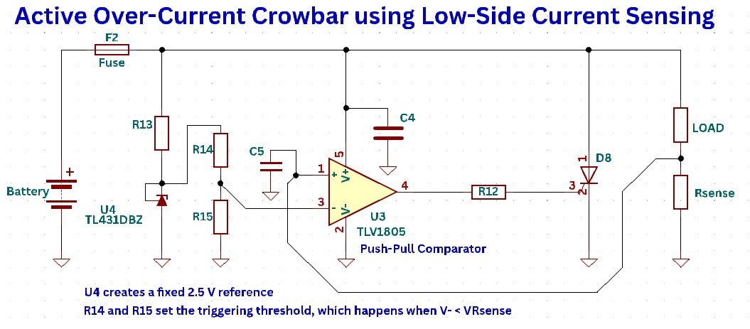
A TL431 Zener shunt regulator is used to create a fixed 2.5 V reference, which is further divided down to create the triggering threshold. When the voltage across the low-side current sense resistor is greater than this threshold, the comparator goes high and triggers the SCR, shorting out the fuse.
Pros of the OCP Crowbar:
- High fault interrupt current rating, given by rating of the fuse.
- One-shot with latching behavior once triggered.
Cons:
- Power supply must be strong enough to short the fuse. If there is current limiting already implemented or a weak battery is used, persistent overcurrent may occur.
- Sensitive, and can be triggered by brief current spikes.
- Not suitable for frequent overcurrent conditions as the fuse must be replaced.
Active Power Management Modules (Low-Cost SSCBs)
Active Power Management Modules are low-cost versions of solid-state circuit breakers, preferred for their fast response time and lack of arc formation upon disconnect. They are made from e-Fuses and power-path management ICs, and are used when both voltage and current protection is desired. Shown below are the Protect Nano (internal FET) and the Protect+ (external FET):
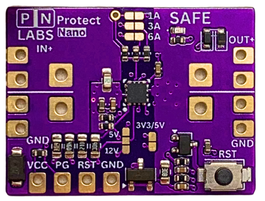
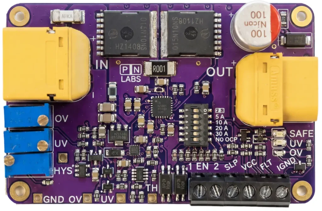
The modules work by driving back-to-back FETs to control the flow of current in both directions, while monitoring the current compared to an adjustable threshold. If the limit is exceeded, the module interrupts the current and latches off until the reset button is pressed or a reset signal is sent.
In addition to current interruption, the module features adjustable voltage cutoffs and reverse current protection which make them very versatile.
Pros of SSCB/APM technology:
- Ultra-fast over-current response time, which is adjustable and resettable using mechanical and electrical means.
- Exceptional efficiency due to use of high-performance N-channel MOSFETs
- Bonus features such as voltage monitoring, soft-start, reverse current blocking make them good candidates for working with batteries.
- Enable switch terminal for direct ON/OFF control.
Cons:
- More expensive than conventional magnetic-thermal circuit breakers, due to increased functionality.
- Fault interrupt current rating is not as high as most circuit breakers or fuses, as the MOSFET SOA must be respected, else it will fail short. For this reason, semiconductor protection methods still use a series fuse as a secondary layer of protection if extremely high fault currents are encountered.
Active Current Limiters (ACLs):
ACLs are devices which attempt to drop the output voltage of your circuit in an attempt to limit the current below a set threshold. If the overcurrent fault is low, the downstream circuitry is not susceptible to brownout, and there is good reason to believe the circuit can resume normal operation upon clearing of the fault, an active current limiter circuit can be desirable. Most DIY bench power supplies implement active current limiting internally.
You can make a DIY active current limiting circuit by driving a high-side MOSFET in its linear region:
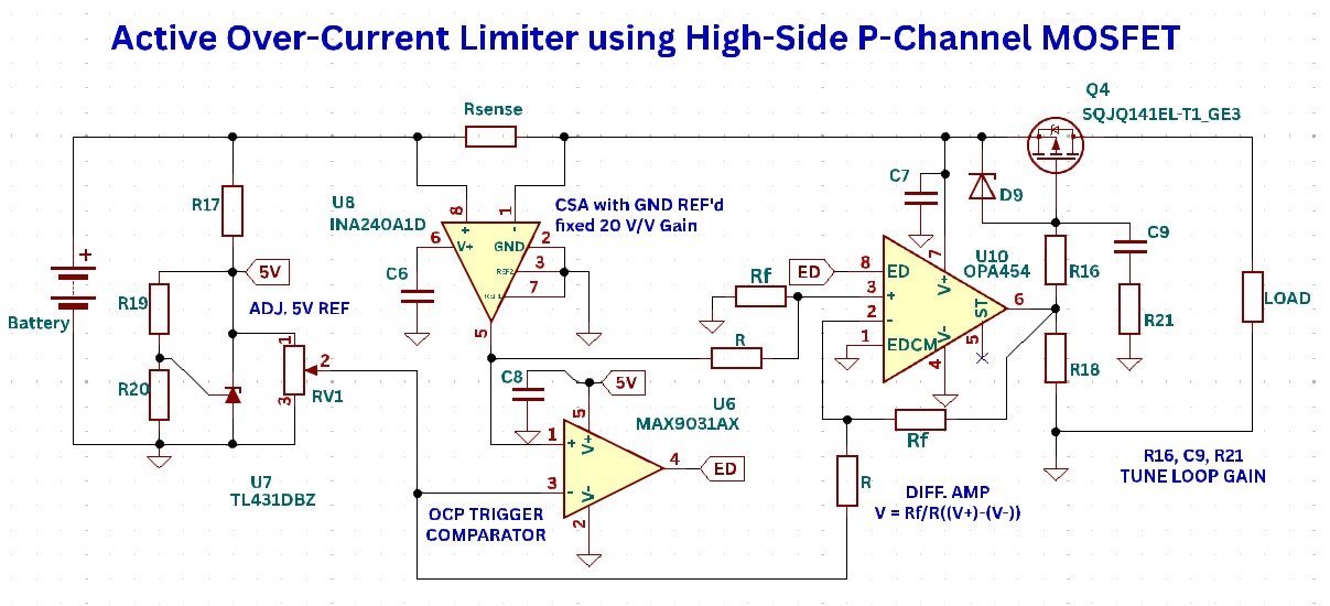
This circuit works by:
- Using the INA240A1D current sense amplifier to measure the voltage across a high-side shunt and amplify it with a fixed gain of 20 V/V
- Comparing the amplified shunt voltage with an adjustable 5 V reference from a TL431 shunt regulator that is tuned via potentiometer RV1.
- Turning on/off an op-amp which implements proportional control (Gain = Rf/R) of the MOSFET to limit the current flowing through the shunt, at which point the comparator will de-activate and shut down the op-amp until the next overcurrent event.
Pros of this Active Current Limiter circuit:
- Auto-recovery after fault has cleared
- Adjustable current limit with potentiometer
Cons:
- Requires heat-sinking of Q4 MOSFET to prevent over-heating in persistent over-current conditions.
- MOSFET gate capacitance requires compensation of op-amp, involving tuning R16, C9, and R21 to ensure overall loop stability.
- Lacks current-foldback or over-temperature shutdown features which enhance MOSFET safety.
- Lack of delay timer, so it is sensitive to over-current and increases the possibility of brownouts during normal transient current events. Modern power-path ICs easily address this by only triggering after the expiration of a timing window controlled by an external capacitor.
Pyrofuses
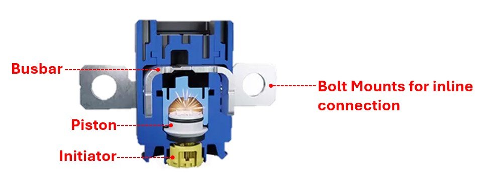
Pyro-fuses are ultra-fast active fuses that use a small explosive charge to sever a high-current bus bar link, and are commonly found in high-voltage DC systems, such as the battery of an EV. The problem with interrupting such a high voltage with a conventional fuse is that an arc will form, and the fuse needs to safely melt away and extinguish that arc (hence why fuses also have voltage ratings).
By having an explosive charge severe the connection, the arc extinguishing capability is greatly increased.
Pros of pyrofuses:
- Ultra-fast response time
- Very high breaking capability and reliability
- One-shot use that ensures swift isolation with precise control
Cons:
- Expensive and only practical for high power, high reliability systems that require it
- Generally bulky
Closing Remarks
The correct over-current protection scheme for any given application depends on the expected fault current, required time to interrupt, interrupt voltage and overall sensitivity of other circuit components. By reading this article and learning more about the different over-current protection techniques, you are better equipped to understand the nuances in selecting the correct one.